Equal slope bands (interference from a plane-parallel plate)
In nature, one can often observe iridescent staining of thin films (oil films on water, soap bubbles, oxide films on metals), resulting from interference of light reflected by two surfaces of the film.
Let on a plane-parallel transparent plate with a refractive index n and thick d at an angle q (Fig. 4.4) a plane monochromatic wave is incident 1 .
On the film surface at point A, the beam is divided into two: it partially reflects from the upper surface of the film, and partially refracts. The refracted ray, reaching point B, is partially refracted into the air ( n \u003d 1), and partially reflect and go to the point WITH. Wave (beam) 2 falling at the same angle as the beam 1 , exactly WITHwill also be reflected. Ray coming out of the film 1 and reflected 2 go in one direction and are coherent if their optical path difference is small compared with the incident wave coherence length. If a collecting lens is placed in their path, then the rays converge at one of the points of the focal plane of the lens and give an interference pattern on the screen, which is determined by the optical path difference.
The optical path difference that arises between two interfering beams, taking into account the half-wave loss when light is reflected from an optically denser medium at a point WITH is equal to:
![]() .
.
The conditions of interference maxima and minima will be respectively equal:
max ![]()
min ![]() .
.
A system of alternating light and dark rings with a common center will appear on the screen. The described interference bands are called bands of equal slope, since each band is formed by beams with the same angle of incidence. When the plate is illuminated with sunlight, interference is observed only if the plate thickness does not exceed a few hundredths of a millimeter. When illuminated with light with a greater degree of coherence (for example, laser radiation), interference is observed when reflected from thicker plates or films.
Stripes of equal thickness (interference from a plate of variable thickness).
Newton's rings
When a film (plate) with a variable thickness is illuminated by a parallel beam of light, a system of interference fringes appears on its surface. Each of the bands arises due to reflection from places of the plate having the same thickness (in the general case, the thickness of the plate can vary arbitrarily). The interference bands resulting from interference from places of the same thickness are called stripes of equal thickness. An example of strips of equal thickness
 are Newton's rings. Newton's rings are observed upon reflection of light from a plane-parallel thick glass plate in contact with each other and a plane-convex lens with a large radius of curvature (Fig. 4.5). The role of a thin film, from the surfaces of which coherent waves are reflected, is played by the air gap (with a varying thickness b
) between the plate and the lens. With normal light incidence, strips of equal thickness have the form of concentric circles, with oblique incidence - ellipses.
are Newton's rings. Newton's rings are observed upon reflection of light from a plane-parallel thick glass plate in contact with each other and a plane-convex lens with a large radius of curvature (Fig. 4.5). The role of a thin film, from the surfaces of which coherent waves are reflected, is played by the air gap (with a varying thickness b
) between the plate and the lens. With normal light incidence, strips of equal thickness have the form of concentric circles, with oblique incidence - ellipses.
The radii of the light and dark Newton's rings are found by the formula:
![]() , m =
1, 2, 3
, m =
1, 2, 3
Even m correspond to the radii of light rings, odd m correspond to the radii of dark rings. Value m \u003d 1 corresponds r \u003d 0, i.e. point at the point of contact of the plate and lens. At this point, a minimum of intensity is observed due to a phase change by p when a light wave is reflected from a plate.
Stripes of equal thickness can also be observed in the wedge-shaped plate. Then the interference fringes are parallel to the edge of the wedge.
Enlightenment Optics
Interference during reflection from thin films is the basis of optical clearing. The passage of light through each refracting surface of the lens is accompanied by a reflection of approximately 4% of the incident light. In complex lenses, such reflections occur many times, and the total loss of light flux reaches a noticeable value. Reflections from the surfaces of the lenses cause glare. In clarified optics, to eliminate light reflection, a thin film of a substance is applied to each free surface of the lens with a refractive index different from that of the lens. The film thickness is selected so that the waves reflected from both of its surfaces extinguish each other. A particularly good result is achieved if the refractive index of the film is equal to the square root of the refractive index of the lens. Under this condition, the intensity of both waves reflected from the film surfaces is the same.
"src \u003d" / c_ec.png "style \u003d" "class \u003d" other "\u003e
Lecture 3
Wave optics
Questions
1. Calculation of the interference pattern from two sources.
2. Light interference in thin films.
3. Newton's rings.
1. Calculation of the interference pattern from two sources
As an example, consider the Young method. The light source is a brightly lit gap Sfrom which a light wave is incident on two narrow equidistant slots S 1 and S 2, parallel slots S. Thus the gaps S 1 and S 2 play the role of coherent sources. Interference pattern (region Sun) observed on screen e , spaced parallel S 1 and S 2. Jung owns the first observation of the phenomenon of interference.
Intensity anywhere M distance screen x from point 0 , determined by the difference in stroke
Δ = L 2 L 1 (1)

 ;
;

 ;
;
 ;
;
Because l >> dthen L 2 + L 1 2 l and
 .
(2)
.
(2)
The maximum condition Δ \u003d mλ;
( m \u003d 0, ± 1, ± 2, ...) 
 .
(3)
.
(3)
Minimum condition  (m \u003d 0, ± 1, ± 2, ...)
 .
(4)
.
(4)
Bandwidth called the distance between two adjacent highs (or lows)
 ,
(5)
,
(5)
interference bandwidth  independent of the order of interference m
and is constant. The main maximum of interference at m
\u003d 0 in the center, from it the maxima of the first ( m
\u003d 1), second ( m
\u003d 2), etc., of orders.
independent of the order of interference m
and is constant. The main maximum of interference at m
\u003d 0 in the center, from it the maxima of the first ( m
\u003d 1), second ( m
\u003d 2), etc., of orders.
For visible light 10 -7 m,  0.1 mm \u003d 10 -4 m (resolution of the eye) interference is observed at l/d
= x/
> 10 3 .
0.1 mm \u003d 10 -4 m (resolution of the eye) interference is observed at l/d
= x/
> 10 3 .
When using white light with a set of wavelengths from violet ( \u003d 0.39 μm) to red ( \u003d 0.75 μm) the boundaries of the spectrum at m \u003d 0, the maxima of all waves coincide; then, at m \u003d 1, 2, ... spectrally colored bands, closer to white purple, then red.
2. Light interference in thin films

Light interference can be observed not only in laboratory conditions with the help of special installations and devices, but also in natural conditions. So, it is easy to observe the rainbow color of soap films, thin films of oil and mineral oil on the surface of water, oxide films on the surface of hardened steel parts (color tarnish). All these phenomena are caused by the interference of light in thin transparent films, which arises as a result of the superposition of coherent waves arising from reflection from the upper and lower surfaces of the film.
Optical path difference 1 and 2

 (6)
(6)where p - refractive index of the film; n 0 is the refractive index of air, n 0 = one; λ 0/2 - the length of the half-wave lost in the reflection of beam 1 at a point ABOUTfrom the interface with an optically denser medium ( n >n 0 ,).
 ;
;
 ;
;


 ;
;

 .
(7)
.
(7)
Maximum condition
 :
(8)
:
(8)
Minimum condition
 :
(9)
:
(9)
When the film is illuminated with white light, it is painted in any specific color, the wavelength of which satisfies the maximum interference. Therefore, by the color of the film, its thickness can be estimated.
Conditions (8), (9) depend on constant values n, 0 from the angle of incidence i and film thickness d, depending on this distinguish equal tilt stripes and stripes of equal thickness.
Equal tilt stripes called interference bands resulting from the superposition of rays incident on a plane-parallel plate at the same angles.
Stripes of equal thickness called interference bands resulting from the superposition of rays incident on a plate of variable thickness from places of the same thickness.
3. Newton's rings

Newton's rings A classic example of strips of equal thickness.
In reflected light, the optical path difference (taking into account the loss of half-wave λ 0/2 when reflected from a plane-parallel plate):
 ,
(10)
,
(10)
where d - gap width.
R 2
=
r 2
+ (R
–
d) 2
(d<<
R)
 .
.
 .
(11)
.
(11)
Maximum condition
light ring radius
:

 (12)
(12)
Minimum condition
dark ring radius
:
 (13)
(13)
The system of light and dark stripes is obtained only when illuminated with monochromatic light. In white light, the interference pattern changes, each bright band turns into a spectrum.
Newton's rings can be observed in transmitted light. Moreover, the maximums of interference in reflected light correspond to the minimums in transmitted light and vice versa.
By measuring the radii of Newton’s rings, we can determine λ 0 (knowing the radius of curvature of the lens R) or R (knowing λ 0).
4. Application of light interference
4.1. Interference spectroscopy wavelength measurement.
4.2. Improving the quality of optical instruments ("Enlightened optics") and the production of highly reflective coatings.

Film thickness dand glass refractive indices n art and films p pl are selected so that when interference in reflected light, the rays 1 and 2или extinguish each other. To do this, their optical path difference must satisfy the condition
 ,
(14)
,
(14)
 ;
;


 .
(15)
.
(15)
Since it is impossible to simultaneously quench all spectral wavelengths, this is usually done for green (λ 0 = 550 nm), to which the human eye is most sensitive (in the radiation spectrum of the sun, these rays have the highest intensity).
In reflected light, lenses with brightened optics appear red-violet. To improve the characteristics of the antireflective coating, it is made of several layers, which “brightens” the optical glasses more uniformly throughout the spectrum.
4.3. Interferometer a device used for accurate (precision) measurement of lengths, angles, refractive indices and density of transparent media, etc.
The interference pattern is very sensitive to the difference in the path of the interfering waves: a negligible change in the path difference causes a noticeable shift in the interference fringes on the screen.
All interferometers are based on the same principle - dividing one beam into two coherent ones - and differ only constructively.

S light source;
R 1 translucent plate;
R 2 transparent plate;
M 1 , M 2 mirrors.
Rays 1 ′ and 2 ′ are coherent, therefore, interference is observed, the result of which will depend on the optical difference of the beam path 1 from point 0 to the mirror M 1 and beam 2 from point 0 to the mirror M 2. By changing the interference pattern, one can judge the small displacement of one of the mirrors. Therefore, the Michelson interferometer is used for accurate (~ 10 -7 m) length measurements.
The most famous experiment, performed by Michelson (together with Morley) in 1887, aimed to detect the dependence of the speed of light on the speed of motion of an inertial coordinate system. As a result, it was found that the speed of light is the same in all inertial systems, which served as an experimental justification for the creation of Einstein's special theory of relativity.
Interference dilatometer a device for changing body length when heated.
Soviet physicist academician V.P. Linnik used the Michelson interferometer principle of operation to create microinterferometer (a combination of an interferometer and a microscope) used to control the cleanliness of the surface treatment of metal products. Thus, the Linnik interferometer is a device designed for visual assessment, measurement and photographing of heights of surface roughness up to the 14th class of surface cleanliness.
Another sensitive optical device is refractometer Rayleigh interferometer. It is used to determine minor changes in the refractive index of transparent media depending on pressure, temperature, impurities, solution concentration, etc. Rayleigh interferometer allows you to measure the change in refractive index with very high accuracy Δ n ~ 10 -6 .
1 . Light interference
1.1. Electromagnetic wave at the interface
When an electromagnetic wave passes through an interface, it is reflected and refracted.
Law of reflection: the reflected beam lies in the same plane with the incident beam and the perpendicular drawn to the interface between the two media at the point of incidence. The angle of incidence is equal to the angle of reflection (Fig. 1.1).

 ,
(1.1)
,
(1.1)
where n 21 relative refractive index of the second medium relative to the first.
To establish the causes of refraction, we write for triangles Abc and ACD (see. Fig. 1.1) relations: Sun = AC sin i 1 , AD = AC sin i 2, then the ratio BC/AD \u003d sin i 1 / sin i 2. Given the transition time of the wave front t and speeds of its distribution v 1 and v 2, respectively, in environments 1 and 2, we have BC = v 1 t and AD = v 2 tfrom where
 .
(1.2)
.
(1.2)
Thus, light is refracted due to different wave speeds in different media. Absolute refractive index of the medium n shows how many times the speed of light in a medium is less than the speed of light in a vacuum: n = c/v.
In accordance with the electromagnetic nature, the speed of light and the refractive index depend on the electromagnetic properties of the medium (its dielectric 0 and magnetic 0)
 .
(1.3)
.
(1.3)

When a wave passes through a media interface (Fig. 1.2), the wavelength changes. Indeed, for v 2 < v 1 (v 1 = c) for the first medium c \u003d , for the second medium v \u003d , then
 and
and  .
.
On segments AD and BC (see. Fig. 1.1) fit the same number of waves.
Consider a change in a plane traveling wave upon transition to another medium. In a vacuum
 ,
,
those. the phase of the wave does not depend on the coordinate x, and from the optical path length nx.

1.2. Light interference and conditions for its observation.
Coherent Light Sources
When the waves are superimposed in space, the phenomenon of interference occurs, which consists in the fact that in some places the waves strengthen each other, and in others weaken. The results of this addition have general laws, regardless of the nature of the wave process.
Interferenceof light is the spatial redistribution of the energy of light radiation when two or more light waves are superimposed, as a result of which in some places there are maxima (light spots), and in others, minima (dark spots) of light intensity.
Everyday experience convinces us that ordinary light sources (for example, incandescent bulbs) do not produce interference phenomena. What is the reason for this? What should be the sources of light waves in order for the phenomenon of interference to occur?
A necessary condition for the interference of waves is their coherence those. the coordinated course in time and space of several oscillatory or wave processes. The coherence conditions are satisfied monochromatic waves - waves unlimited in space of one definite and strictly constant frequency ( \u003d const).
Real light waves are not strictly monochromatic. For fundamental physical reasons, radiation always has a statistical character. Atoms of a light source emit independently from each other at random times, and the radiation of each atom lasts a very short time (τ ≤ 10 –8 s). The resulting radiation of the source at each moment of time consists of the contributions of a huge number of atoms. After a time of the order of τ, the entire set of radiating atoms is updated. Therefore, the total radiation will have a different amplitude and, most importantly, a different phase. The phase of the wave emitted by a real light source remains approximately constant only at time intervals of the order of τ.
The intermittent emission of light by atoms in the form of separate short pulses is called wave train. The average duration of one train is called coherence time τ coh. In accordance with the condition of temporal coherence, the coherence time cannot exceed the radiation time:
τ coh< τ . (1.4)
During wave propagation, the oscillation phase is retained only during the coherence time, during which time the wave propagates in vacuum over a distance l coh \u003d withτ coh - coherence lengths (train lengths). Coherence length l coh is the distance, during the passage of which two or more waves lose coherence. In accordance with the condition of spatial coherence, the optical path difference cannot exceed the coherence length:
L < l coh (1.5)
The waves emitted by two independent light sources (even two independent atoms) are not coherent, since the phase difference between the radiation of these sources randomly changes every 10 -8 s. This leads to averaging of the intensity at each point in space. Therefore, incoherent rays do not create a stable, invariable in time interference pattern.
Moreover, since trains of waves emitted by the same atom at different instants of time ( ∆ t > 10 -8 s), differ in frequency and phase, then, obviously, interference will occur only when the waves formed from the same train meet.

As an example, consider the Young method. A brightly lit slot serves as a light source. S (Fig. 1.1), from which a light wave is incident on two narrow equidistant slots S 1 and S 2, parallel slots S. Thus the gaps S 1 and S 2 play the role of coherent sources. Interference pattern (region Sun) is observed on screen E , spaced parallel S 1 and S 2. Jung owns the first observation of the phenomenon of interference.
The interference pattern on the screen (see Fig. 1.4) has the form of stripes parallel to the slit. If the source S emits monochromatic light (of the same color of the same frequency ν), then the interference pattern is an alternation of light and dark bands these are maxima of the minimum interference.
What determines the result of interference at any point on the screen? In what cases will the waves cancel each other, in which cases will they amplify?
Consider two cases:
1) light propagates in a vacuum ( n 0 = 1);
2) light propagates in media with different refractive indices ( n 1 ≠ n 2 ≠ 1).
1. Let both coherent beams from sources S 1 and S 2 go the way l 1 and l 2 see you in t. Mscreen in a vacuum (Fig. 1.5). In this case l 1 and l 2 - geometric paths of rays. We calculate the result of superposition of two sinusoidal coherent waves at an arbitrary point M screen. Let's do it for the electric vector
 (we should not forget that in a homogeneous medium the light intensity is proportional to the square of the amplitude of the intensity vector I ≈ E 2).
Oscillations coming to a point M from sources S 1 and S 2 are described by the equations:
 ,
,

 ,
,where λ 0 is the wavelength in vacuum.
According to the principle of wave superposition, the amplitude of the resulting oscillation in t. M defined by the formula
for intensities
where  and
and 
(1.8)
(1.8)
phases of folding oscillations.
From the expression (1.7) it follows that the magnitude of the amplitude of the resulting oscillation E 0, and, hence, intensity, depends only on the phase difference (φ 1 –φ 2) of the added oscillations.
So the waves are called coherentif at an arbitrary point of their meeting the phase difference of the oscillations remains constant in time .
In this case, two limiting options are possible.
but) (φ 1 φ 2) \u003d ± 2 kπ ( k= 0, 1, 2, ...), (1.9)
cos (φ 1 - φ 2) \u003d 1; E 0
= E 01
+ E 02
;
 ,
,
those. the amplitude and intensity of the resulting oscillation is maximum (in the case of E 01 = E 02 E 0 = 2E 01 , , a I = 4I 01).
From equations (1.6) we find the phase difference
 ,
(1.10)
,
(1.10)
where Δ l = (l 2 - l 1) geometric path difference waves from sources S 1 and S 2 to t . M screen (see. Fig. 1.5).
From formulas (1.9) and (1.10) it follows that the condition of interference maximum
 ,
(1.11)
,
(1.11)
where k the order of the interference maximum ( k\u003d 0, 1, 2, ..., with k \u003d0 observe the maximum in the center of the screen).
b) (φ 1 - φ 2) \u003d ± (2 k + 1) π ( k= 0, 1, 2, ...), (1.12)
cos (φ 1 - φ 2) \u003d –
1; E 0
= E 01
–
E 02
;
 ,
,
those. the amplitude of the resulting oscillation, and, consequently, the intensity is minimal (in the case of E 01 = E 02 E 0 = 0 and I = 0).
From formulas (1.10) and (1.11) the interference condition follows minimum
 ,
(1.13)
,
(1.13)
where k - the order of the interference minimum.
2. If coherent rays travel their paths to a point M in different environments: first – way l 1 in a refractive index medium p 1 , second – way l 2 , in a refractive index medium n 2, the conditions for the formation of interference maxima and minima will depend not on the geometric path difference Δ l = (l 2 - l 1), and from opticalstroke differences
Δ L = L 2 – L 1 = l 2 n 2 – l 1 n 1 ,(1.14)
where L 1 , and L 2 – optical paths of rays 1 and 2, L 1 = l 1 P 1 ; L 2 = l 2 n 2 . In this case, the phase difference of the added waves
where with Is the speed of light in vacuum, v - the speed of light in the medium; λ is the wavelength, λ = v/ ; is the frequency. For vacuum λ 0 = with/, and for a medium with a refractive index n λ = λ 0 / n.
Equating (1.11) and (1.12) in turn to (1.15), we obtain the condition of interference maxima:
![]() ,
(1.16)
,
(1.16)
and interference lows:
 ,
(1.17)
,
(1.17)
where k = 0, 1, 2, 3, … .
So, in those places on the screen to which an even number of half-waves fit in the optical difference in the path of the rays, the vibrations coming from both sources add up, the amplitude doubles, and the intensity increases 4 times. In those places of the screen to which an odd number of half-waves fit in the optical path difference, the vibrations come in the opposite phase and completely cancel each other out.
Note 1 to entry:
1. From the formula (1.15), a relationship is found between the phase difference and the optical path difference:
 .
.

The result of calculating the interference pattern from two coherent sources can be given by the example of Jung's experiment. Cracks S 1 and S 2 (Fig. 1.6) are at a distance d from each other and are coherent light sources. Interference is observed at an arbitrary point M screen parallel to both slots at a distance L , moreover L >> d . The origin is selected in the volume of the screen, located symmetrically relative to the slots S 1 and S 2 .
Intensity anywhere M distance screen x from point 0, determined by the difference in stroke Δ l = l 2 l 1 (see Fig. 1.6).
The intensity maxima will be observed at
x max = ± kLλ 0 / d (k = 0, 1, 2, ...),(1.18)
intensity minimums - at
x min = ± (2k +1) Lλ 0/2 d (k= 0, 1, 2, ...).(1.19)
The distance between two adjacent maximums or minimums, called the width of the interference band,
Δ x = Lλ 0 / d . (1.20)
From the formula (1.20) it is seen that the width of the interference band Δ xindependent of the order of interference (values k) and is constant for data L , d. and λ 0. According to the measured values L , d. and λ 0, using (1.20), it is possible to experimentally determine the light wavelength λ 0.
1.2. Light interference in thin films
Light interference can be observed not only in laboratory conditions with the help of special installations and devices, but also in natural conditions. So, it is easy to observe the rainbow color of soap films, thin films of oil and mineral oil on the surface of water, oxide films on the surface of hardened steel parts (color tarnish). All these phenomena are caused by the interference of light in thin transparent films, which arises as a result of the superposition of coherent waves arising from reflection from the upper and lower surfaces of the film.
The study of interference in thin films allows one to determine a number of practically important quantities – film thickness, its refractive index, heating temperature for hardening parts, radiation wavelength, etc.
The scheme of occurrence of light interference in reflected light is shown in Fig. 1.7. Thick film d a plane monochromatic wave (λ 0 = const) at an angle i. Suppose that on both sides of a refractive index film n the same medium is located (e.g. air with a refractive index n 0 = 1).
Consider one beam incident on the upper surface of the film. On the surface of the film at a point ABOUT the incident beam will be divided into two: the first (1) – reflected from the top surface of the film, the second (2) – refracts. Refracted beam reaching the point WITH, partially refracts into the air, and partially reflects and goes to the point AT.

The result of interference at a point M determined by the optical path difference of rays 1 and 2. The optical path difference, these rays gain from point O to the plane AB , which was the front of the secondary (reflected) rays. Front AB perpendicular to rays 1 and 2.
So, the optical path difference 1 and 2
 ,
(1.21)
,
(1.21)
where p – film refractive index; n 0 – refractive index of air n 0 = one; and λ 0/2 is the length of the half-wave lost in the reflection of beam 1 at a point ABOUTfrom the interface with an optically denser medium ( n > n 0).
Using expression (1.21) for the optical path difference, the conditions of the maximums and minimums of interference, as well as the law of refraction, we obtain:
 ,
(1.22)
,
(1.22)
where k \u003d 0, 1, 2, ... (in this case, the reflected rays will be maximally amplified, i.e., maximum interference is observed);
 ,
(1.23)
,
(1.23)
(in this case, the greatest attenuation of the reflected rays is observed - a minimum of interference).
When the film is illuminated with white light, it is painted in any specific color, the wavelength of which satisfies the maximum interference. Therefore, by the color of the film, its thickness can be estimated.
Interference is also observed in passingthe light. Optical travel difference (Δ L) for transmitted light differs from its value for reflected light by λ 0/2. Therefore, the maximum interference in reflected light for a given wavelength corresponds to the minimum interference in transmitted light, i.e. in reflected and transmitted light, the film is painted in additional (to white) colors.
The possibility of attenuation of reflected light due to interference in thin films is widely used in modern optical instruments (cameras, binoculars, periscopes, microscopes, etc.) to improve their quality. The method of obtaining highly reflective coatings and improving the quality of optical instruments is called "optics enlightenment".
The passage of light through each refractive surface of the lens, for example, through the glass стекло air interface, is accompanied by a reflection of ~ 4% of the incident flux (at a glass refractive index n \u003d 1.5). Since modern lenses contain a large number of lenses, the loss of light flux due to reflections is large. As a result, the transmitted light intensity is weakened, and the aperture ratio of the optical device decreases. In addition, reflection from the lens surfaces leads to glare, which, for example, in military equipment, unmasks the location of the device. To eliminate these disadvantages carry out the so-called enlightenment of optics. For this purpose, thin films with a refractive index lower than the refractive index of the lens material are applied to the surface of the lenses (1 < n < n Art). When light is reflected from the air film and film glass interfaces, interference occurs between coherent rays 1 and 2 возникает (Fig. 1.8).
Film thickness d and glass refractive indices n art and films p pl are selected so that when interference in reflected light, the rays 1 and 2или extinguish each other. For this, their optical path difference must satisfy condition (1.17). Since half-wave losses occur on both surfaces of the film, and the light falls normally (angle of incidence i = 0), the minimum condition in reflected light is written as follows:
 ,
(1.24)
,
(1.24)
where 2 d · n pl - the optical difference in the path of the rays 1 and 2. The film thickness is chosen to be minimal ( k \u003d 0). Then

Since it is impossible to simultaneously quench all spectral wavelengths, this is usually done for green (λ 0 = 550 nm), to which the human eye is most sensitive (in the radiation spectrum of the sun, these rays have the highest intensity).
In reflected light, lenses with brightened optics appear red-violet. This, of course, somewhat distorts the color rendering in the image. To improve the characteristics of the antireflective coating, it is made of several layers, which “brightens” the optical glasses more uniformly throughout the spectrum.
When studying the interference of light in thin films, bands of equal slope and equal thickness are distinguished.
From the expressions (1.22, 1.23) it follows that for the data λ 0 , d, and p Each angle of incidence of the rays corresponds to its own interference band. The interference lines resulting from the superposition of rays incident on a plane-parallel plate at the same angles are called stripes of equal slope.
If the film has a variable thickness d ≠ const , but λ 0 , nand i unchanged, then on the screen there is a system of interference bands called stripes of equal thickness. Each of the bands arises due to reflection from places of the film having the same thickness.
A classic example of strips of equal thickness are newton's rings. They are observed when light is reflected from the air gap formed by a plane-parallel plate and a plane-convex lens in contact with it with a large radius of curvature R (Fig. 1.9). In this case, the light falls normally on the flat surface of the lens. When superimposed rays reflected from the upper and lower surfaces of the air wedge, interference strips of equal thickness appear, having the form of concentric circles (Newton's rings).

 ,
,
where d – gap width. From fig. 1.9 it follows that
R 2 = r 2 + (R – d) 2 ,
where R – lens curvature radius; r – radius of Newton's ring (all points of the ring correspond to the same thickness d clearance). Given that d << Rwe get d = r 2 /2R. Therefore
 .
(1.26)
.
(1.26)
Rainbow color of soap bubbles or gasoline films on water occurs as a result of interference of sunlight reflected by two surfaces of the film.
Let on a plane-parallel transparent film with a refractive index pand thick dat an angle a plane monochromatic wave with a length of (Fig. 4.8).

Fig. 4.8. Thin film light interference
The interference pattern in reflected light occurs due to the superposition of two waves reflected from the upper and lower surfaces of the film. Consider the addition of waves emerging from a point WITH. A plane wave can be represented as a beam of parallel rays. One of the rays of the beam (2) directly hits the point WITHand reflected (2 ") in it upward at an angle equal to the angle of incidence. Another beam (1) hits the point WITH in a more complicated way: at first it is refracted at a point BUT and propagates in the film, then it is reflected from its lower surface at the point 0 and finally comes out, refracted, out (1 ") at the point WITH at an angle equal to the angle of incidence. So at the point WITH the film throws up two parallel beams, of which one was formed due to reflection from the lower surface of the film, the second due to reflection from the upper surface of the film. (Beams resulting from multiple reflections from film surfaces are not considered due to their low intensity.)
The optical path difference acquired by beams 1 and 2 before they converge at a point WITHis equal to
Assuming the refractive index of air and taking into account the ratio


|
|

We use the law of refraction of light
In this way,
|
|
In addition to the optical travel difference , should take into account the phase change of the wave upon reflection. At the point WITH at the air interface – film "is reflected from optically denser medium, that is, a medium with a high refractive index. At not too large angles of incidence, in this case, the phase undergoes a change in . (The same phase jump occurs when a wave traveling along a string is reflected from its fixed end.) At the point 0 at the film – air interface, light is reflected from an optically less dense medium, so that a phase jump does not occur.
As a result, between the rays 1 "and 2" an additional phase difference arises, corresponding, as follows from formula (4.12), to the optical path difference, which can be taken into account if decrease or increase by half the wavelength in a vacuum.
Therefore, when the relation
it turns out maximum interference in reflected light, and in the case of
in reflected light is observed minimum.
Thus, when light falls on a gasoline film in water, depending on the angle of view and film thickness, a rainbow color of the film is observed, indicating the amplification of light waves with certain lengths l.Interference in thin films can be observed not only in reflected but also in transmitted light.
As already noted, for the appearance of the observed interference pattern, the optical path difference of the interfering waves should not exceed the coherence length, which imposes a limitation on the film thickness.
Example.On a soap film ( n \u003d 1.3), which is in the air, a normal beam of white light falls. Determine at which smallest thickness dfilm reflected light with a wavelength μm will be maximized as a result of interference.
From the condition of the interference maximum (4.28), we find for the film thickness the expression
(angle of incidence ). Minimum value d It turns out at:
![]()
In nature, one can observe the rainbow coloring of thin films (oil films on water, soap bubbles, oxide films on metals), which arises as a result of interference of light reflected by two surfaces of the film.
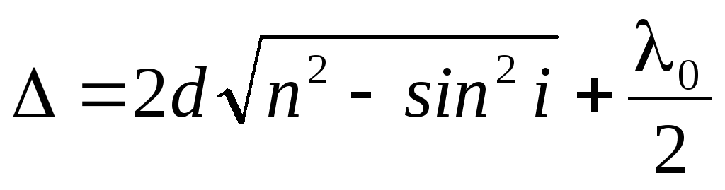
Let on a plane-parallel transparent film with a refractive index p and thick d at an angle i a plane monochromatic wave is incident (consider one ray). We assume that the same medium (for example, air) and is located on both sides of the film. Part of the front of the incident wave, perpendicular to the plane of the drawing, is depicted as a segment AB (direction of wave propagation, i.e., rays 1 and 2). On the film surface in T. A, the beam is divided into two: it partially reflects from the upper surface of the film, and partially refracts. Refracted beam, reaching t .D, partially refracts into the air, and partially reflects and goes to t. C. Here he again partially reflects (due to the low intensity we do not consider) and refracts, entering the air at an angle i. Refracted wave (ray 1’’ ) is superimposed on the wave directly reflected from the upper surface (beam 2’) . Rays emerging from the film / ’, 1 ’’ and 2 ’coherent if the optical difference of their path is small compared to the coherence length of the incident wave. If on their way to put a collecting lens, then they converge in one of t. R focal plane of the lens and will give an interference picture. When a light wave falls on a thin transparent plate (or film), reflection from both surfaces of the plate occurs. As a result, two light waves arise, which under certain conditions can interfere. The optical path difference arising between two interfering rays from t. BUT to the plane Sunwhere the term is due to the loss of half-wave upon reflection of light from the interface.
If n\u003e n 0then the half-wave loss will occur in t. BUTand will have a minus sign, if n ![]() where is the refracted angle (9.1)
where is the refracted angle (9.1)
If n\u003e n 0, .
At the point R will be maximum if ![]() or
or ![]() (9.2)
(9.2)
Minimum if or (9.3)
When the film is illuminated with white light, for some wavelengths the condition of maximum reflection is satisfied, for some others - a minimum. Therefore, in reflected light, the film appears colored.
Interference is observed not only in reflected light, but also in light passing through the film, but because Since the optical path difference for transmitted light differs from that for reflected light by, then the maximums of interference in reflected light correspond to the minimums in transmitted light, and vice versa. Interference is observed only if the doubled plate thickness is less than the incident wave coherence length.
1. Equal Tilt(interference from a plane-parallel plate).

 Def. 9.1. The interference fringes resulting from the superposition of rays incident on a plane-parallel plate at the same angles are called stripes of equal slope.
The rays / / and / //, reflected from the upper and lower faces of the plate, are parallel to each other, since the plate is plane-parallel. T.O. rays 1 "and I" “Intersect” only at infinity, so they say that equal slope bands are localized at infinity. For their observation using a collecting lens and a screen (E) located in the focal plane
Rays / "and /" / will gather in focus F lenses (in Fig. its optical axis is parallel to the rays G and / "), other rays will come to the same point (ray 2), parallel to the ray /, the overall intensity increases. Rays 3, tilted at a different angle, will assemble in another t. R focal plane of the lens. If the optical axis of the lens is perpendicular to the surface of the plate, then strips of equal slope will have the form of concentric rings centered on the focus of the lens.
Task 1 A beam of monochromatic light normally falls onto a thick glass plate coated with a very thin film. Reflected light is maximally attenuated due to interference. Determine the film thickness.
Given: Solution:
Because the refractive index of air is less than the refractive index of the film, which in turn is less than the refractive index of glass, then in both cases the reflection comes from a medium optically denser than the medium in which the incident beam is traveling. Therefore, the phase of the oscillations changes twice and the result will be the same as if there was no phase change. Minimum condition:, where not taken into account,, and. Assuming,,, etc.
2.  Stripes of equal thickness (interference from a plate of variable thickness). Let a plane wave fall on the wedge (the angle a between the side faces is small), the propagation direction of which coincides with the parallel rays / and 2. Pconsider the rays / / and / // reflected from the upper and lower surfaces of the wedge. With a certain mutual position of the wedge and lens rays / / and 1"
intersect in some t. BUT, being a point image AT. Since the rays / / and / // are coherent, they will interfere. If the source is located far from the surface of the wedge and the angle but sufficiently small, then the optical path difference between the rays / / and / // can be calculated by the formula (10.1), where as d the thickness of the wedge is taken at the point where the beam falls on it. The rays 2"
and 2",
formed by beam splitting 2,
falling to another point of the wedge, are collected by a lens in t. BUT". The optical path difference is determined by the thickness d ".A system of interference fringes appears on the screen. Each of the bands arises due to reflection from places of the plate having the same thickness.
Stripes of equal thickness (interference from a plate of variable thickness). Let a plane wave fall on the wedge (the angle a between the side faces is small), the propagation direction of which coincides with the parallel rays / and 2. Pconsider the rays / / and / // reflected from the upper and lower surfaces of the wedge. With a certain mutual position of the wedge and lens rays / / and 1"
intersect in some t. BUT, being a point image AT. Since the rays / / and / // are coherent, they will interfere. If the source is located far from the surface of the wedge and the angle but sufficiently small, then the optical path difference between the rays / / and / // can be calculated by the formula (10.1), where as d the thickness of the wedge is taken at the point where the beam falls on it. The rays 2"
and 2",
formed by beam splitting 2,
falling to another point of the wedge, are collected by a lens in t. BUT". The optical path difference is determined by the thickness d ".A system of interference fringes appears on the screen. Each of the bands arises due to reflection from places of the plate having the same thickness.
Def. 9.2. The interference fringes arising as a result of interference from places of the same thickness are called. stripes of equal thickness.
Since the upper and lower edges of the wedge are not parallel to each other, the rays / / and / // {2" and 2"} intersect near the plate. In this way, strips of equal thickness are localized near the surface of the wedge. If light falls on the plate normally, then strips of equal thickness are localized on the upper surface of the wedge. If we want to get an image of the interference pattern on the screen, then the collecting lens and screen need to be positioned in relation to the wedge so that the image of the upper surface of the wedge is visible on the screen.
To determine the width of interference fringes in the case of monochromatic light, we write the condition for two adjacent interference maxima ( mth and m + 1- th orders) by the formula 9.2: ![]() and
and ![]() from where. If the distances from the edge of the wedge to the considered interference bands are equal to and, then
from where. If the distances from the edge of the wedge to the considered interference bands are equal to and, then ![]() and, where is the small angle between the edges of the wedge (refracting the angle of the wedge), i.e. . In view of the smallness, the refracting angle of the wedge should also be very small, since otherwise, strips of equal thickness will be so closely spaced that they cannot be distinguished.
and, where is the small angle between the edges of the wedge (refracting the angle of the wedge), i.e. . In view of the smallness, the refracting angle of the wedge should also be very small, since otherwise, strips of equal thickness will be so closely spaced that they cannot be distinguished.
Task 2 A beam of monochromatic light beams normally falls on a glass wedge to its face. The number of interference bands per 1 cm is 10. Determine the refracting angle of the wedge.
Given: Solution:
 A parallel beam of rays, falling normally to the edge of the wedge, is reflected both from the upper and from the lower face. These rays are coherent, therefore, a stable pattern of interference is observed. Because Since interference fringes are observed at small wedge angles, the reflected rays will be almost parallel. Dark bands will be observed in those sections of the wedge for which the difference in the walking rays is equal to an odd number of half-waves: or, since then. Let an arbitrary dark strip of the number correspond to a certain thickness of the wedge in this place, and the dark strip of the number corresponds to the thickness of the wedge in this place,. According to the condition, 10 bands fit in, then, because then
  .
.
 3. Newton's rings. Newton's rings are an example of strips of equal thickness. They are observed when light is reflected from the air gap formed by a plane-parallel plate and a plane-convex lens with a large radius of curvature in contact with it. A parallel beam of light falls on the flat surface of the lens and is partially reflected from the upper and lower surfaces of the air gap between the lens and the plate, i.e. reflected from optically denser media. In this case, both waves change the phase of the oscillations by and no additional travel difference arises. When superimposed by reflected rays, bands of equal thickness arise, with normal incidence of light having the form of concentric circles.
AT reflected light optical path difference at i \u003d 0: ![]() ,
where to find R ..
,
where to find R ..
Both for strips of equal slope and for strips of equal thickness the position of the maxima depends on . The system of light and dark stripes is obtained only when illuminated with monochromatic light. When observed in white light, a set of displaced relative to each other bands formed by beams of different wavelengths is obtained, and the interference pattern acquires a rainbow color. All reasoning was carried out for reflected light. Interference can be observed and in transmitted light moreover, in this case no half-wave loss is observed - the optical path difference for transmitted and reflected light will differ by / 2, t. the maxima of interference in reflected light correspond to the minima in transmitted light, and vice versa.